Intrinsic safety is one of the safest ways to ensure that an electrical device installed in a hazardous location cannot result in a fire or an explosion.
This content is courtesy of the Hazloc Directory with who we are affiliated with.
It’s important to understand what intrinsic safety is and how it is achieved. In this document, we’re going to focus on:
-
The basic principles of intrinsic safety
-
The three components of an intrinsically safe system
-
How the components connect and work together to become an intrinsically safe system
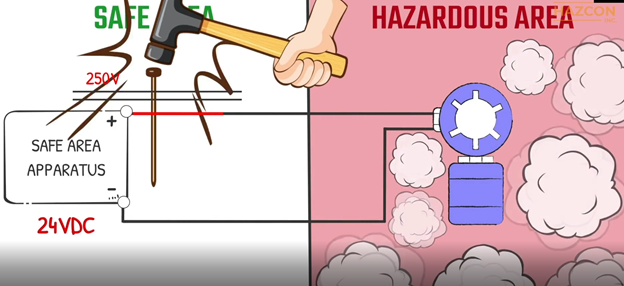
To demonstrate why it is critical that electrical equipment be protected in a hazardous location, let’s look at the installation of an electrical circuit in such an area without any protection.
An electrical sensor is placed in a hazardous location. Power is fed to it from a safe area, outside the hazardous location. If a fault happens within the safe area, a voltage of 250 volts or even higher can enter the hazardous area.
Furthermore, if a fault happens within our electrical sensor located inside the hazardous area, a high value short circuit current can flow into the hazardous location from our power supply.
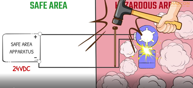
In both of these fault conditions, excess temperature, arcs, and sparks can ignite the explosive atmosphere present.
Intrinsic safety is a highly effective protection technique, based on the principle of limiting the thermal and electric energy within the equipment and its interconnecting wiring.
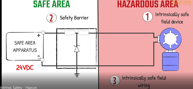
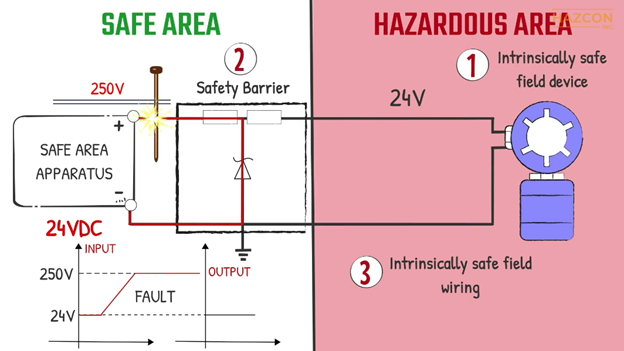
An Intrinsic safety system involves three main components:
- An intrinsically safe field device
- A safety barrier, the energy limiting device
- Intrinsically safe field wiring which connects the barrier to the field device
Intrinsic safety is a system concept, and it is necessary to consider the safety of each component of the system.
The safety barrier limits the maximum amount of voltage, current and power transferring to the field device to safe levels. Under normal operation, the barrier is not needed as a safety device. The input voltage and current from the power source, for example, may be transferred directly to the field device without any changes.
If a fault happens on the controller, on the other hand, and 250 volts is delivered to the input terminals of our safety barrier, the output voltage remains the same as the maximum allowable value, in our case 24 volts for example.
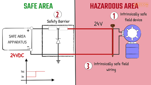
Similarly, if a fault happens within our field device located inside the hazardous area, the safety barrier limits this faulted current to the allowable maximum level that can flow into the hazardous location from our controller.
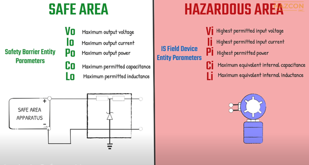
It may be clear to you, from these graphics, that the safety barrier and the field device must be compatible.
“Entity concept” is a globally recognized method that specifies the maximum energy a given safety barrier can ever deliver. The same method specifies the maximum energy a given field device can ever receive and still be safe.
For the safety barrier, the maximum allowable values apply to the maximum amount of voltage, current and power the safety barrier can deliver to a hazardous area, as well as the maximum permitted capacitance and inductance that may be safely connected to the output of the safety barrier.
For the IS field device, the entity parameters relate to the maximum allowable amount of voltage, current and power which may be received as an input, as well as the equivalent internal capacitance and inductance.
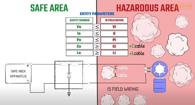
The voltage output of the safety barrier must be less than the voltage of the field device. The same relationship is true for current and power.
The maximum equivalent internal capacitance of the intrinsically safe device must be less than the maximum allowed capacitance of the barrier. The same is true of the inductance value.
Because the field wiring cables have capacitance and inductance values, these values must also be taken into account. The total capacitance of the intrinsic safety system is therefore the capacitance of the field device plus the capacitance of the cables. This total must be less than the maximum permitted value of the barrier. Similarly, the total inductance of the system must be less than the inductance of the safety barrier.
Let’s look at a design that is being considered. Test your understanding of the intrinsic safety system concept. Would this system be safe? Why or why not?
This system includes an intrinsically safe field device with the following listed entity parameters:
- The input voltage is 30 volts (Ui = 30 V), and the input current of the field device is 110 milli-amps (Ii = 110 mA)
- Maximum internal capacitance is 20 nano-farads (Ci = 20 nF) and the maximum internal inductance is 5 microhenries (5 µH)
- Output voltage 24 Volts (Uo = 24 V)
- Output current 125 milli-amps (Io = 125mA)
- The maximum allowable capacitance is 100 nano-farads (Co = 100nF), and the maximum allowable inductance is 35 microhenries (35 µH)
20 meters of cables connect the safety barrier to the field device.
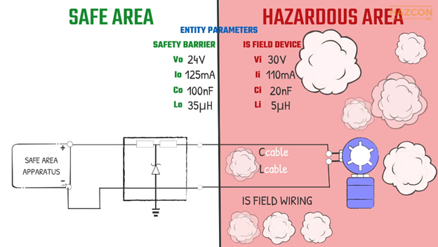
Would this system be safe?
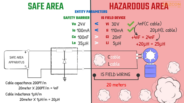
As we can see, the maximum output voltage of the barrier is less than the maximum allowed input voltage of the IS device. This is safe.
The maximum output current of the barrier is higher than the maximum permitted input current of the field device. Therefore, the use of this barrier is not safe in combination with this device. We need to choose a barrier with less output current. If we choose a barrier with an output current of 100 milliamps, for instance, this aspect of the intrinsic safety system is now safe.
But we still need to consider the capacitance and inductance values. The maximum equivalent capacitance of the intrinsically safe device is less than the maximum permitted capacitance that can be connected to the barrier.
Also, the maximum equivalent inductance of the IS device is less than maximum permitted inductance that can be connected to the barrier.
But what about the connecting cables? If we consider 200 picofarads per meter for the capacitance of the cable and 1 microhenry per meter for the inductance value of the cable, then the installation is safe with 20 meters connecting cables. The wiring connection can be longer as long as the total inductance and capacitance of the cables and the intrinsically safe device are less than the permitted values of the barrier.
In summary:
As we can see, the maximum output voltage of the barrier is less than the maximum allowed input voltage of the IS device. This is safe.
The maximum output current of the barrier is higher than the maximum permitted input current of the field device. Therefore, the use of this barrier is not safe in combination with this device. We need to choose a barrier with less output current. If we choose a barrier with an output current of 100 milliamps, for instance, this aspect of the intrinsic safety system is now safe.
But we still need to consider the capacitance and inductance values. The maximum equivalent capacitance of the intrinsically safe device is less than the maximum permitted capacitance that can be connected to the barrier.
Also, the maximum equivalent inductance of the IS device is less than maximum permitted inductance that can be connected to the barrier.
But what about the connecting cables? If we consider 200 picofarads per meter for the capacitance of the cable and 1 microhenry per meter for the inductance value of the cable, then the installation is safe with 20 meters connecting cables. The wiring connection can be longer as long as the total inductance and capacitance of the cables and the intrinsically safe device are less than the permitted values of the barrier.
This article was provided by Hazcon Inc.


